2. Create 3 private networks namely N1, N2 and N3, Send the data from N1 to N2. If the packets are transferring from N3, it shouldn't accept the packets. Accordingly develop the security features.Create 3 private networks namely N1, N2 and N3, Send the data from N1 to N2. If the packets are transferring from N3, it shouldn't accept the packets. Accordingly develop the security features.
In Cisco Packet Tracer, you can simulate this scenario by configuring access control lists (ACLs) on routers to control the flow of traffic between the networks. Here's a basic example:
Procedure
1. **Create the Networks:**
- Place three routers on the workspace and label them R1, R2, and R3.
- Connect the routers as follows:
- Connect R1 to R2 and R3.
- Connect R2 to R3.
- Assign IP addresses to the router interfaces for each network (N1, N2, N3).
2. **Configure Router ACLs:**
- Access the CLI of each router.
For R1 (assuming FastEthernet interfaces):
```bash
enable
configure terminal
interface FastEthernet0/0
ip address <N1_IP> <Subnet_Mask>
exit
interface FastEthernet0/1
ip address <N2_IP> <Subnet_Mask>
exit
access-list 100 deny ip any <N3_IP> <Subnet_Mask>
access-list 100 permit ip any any
interface FastEthernet0/0
ip access-group 100 in
```
For R2:
```bash
enable
configure terminal
interface FastEthernet0/0
ip address <N2_IP> <Subnet_Mask>
exit
interface FastEthernet0/1
ip address <N3_IP> <Subnet_Mask>
exit
```
For R3:
```bash
enable
configure terminal
interface FastEthernet0/0
ip address <N3_IP> <Subnet_Mask>
exit
```
Replace `<N1_IP>`, `<N2_IP>`, and `<N3_IP>` with actual IP addresses for each network.
3. **Test Connectivity:**
- With this setup, R1 will deny any packets coming from N3.
- You can test this by using the `ping` command on devices within N1 and N2. They should be able to communicate, but communication between N1 and N3 should be denied.
Remember, this is a basic example and actual configurations may vary based on your network topology and the router models used in Packet Tracer. Ensure that you adapt the configuration based on your specific requirements and network setup.
Steps to Configure and Verify Three Router Connections in Cisco Packet Tracer using RIP Routing:
Step 1: First, open the Cisco packet tracer desktop and select the devices given below:
| S.NO | Device | Model Name | Qty. |
|---|---|---|---|
| 1. | PC | PC | 6 |
| 2. | Switch | PT-Switch | 3 |
| 3. | Router | PT-router | 3 |
IP Addressing Table:
| S.NO | Device | IPv4 Address | Subnet mask | Default Gateway |
|---|---|---|---|---|
| 1. | PC0 | 192.168.10.2 | 255.255.255.0 | 192.168.10.1 |
| 2. | PC1 | 192.168.10.3 | 255.255.255.0 | 192.168.10.1 |
| 3. | PC2 | 192.168.20.2 | 255.255.255.0 | 192.168.20.1 |
| 4. | PC3 | 192.168.20.3 | 255.255.255.0 | 192.168.20.1 |
| 5. | PC4 | 192.168.30.2 | 255.255.255.0 | 192.168.30.1 |
| 6. | PC5 | 192.168.30.3 | 255.255.255.0 | 192.168.30.1 |
- Then, create a network topology as shown below the image.
- Use an Automatic connecting cable to connect the devices with others.
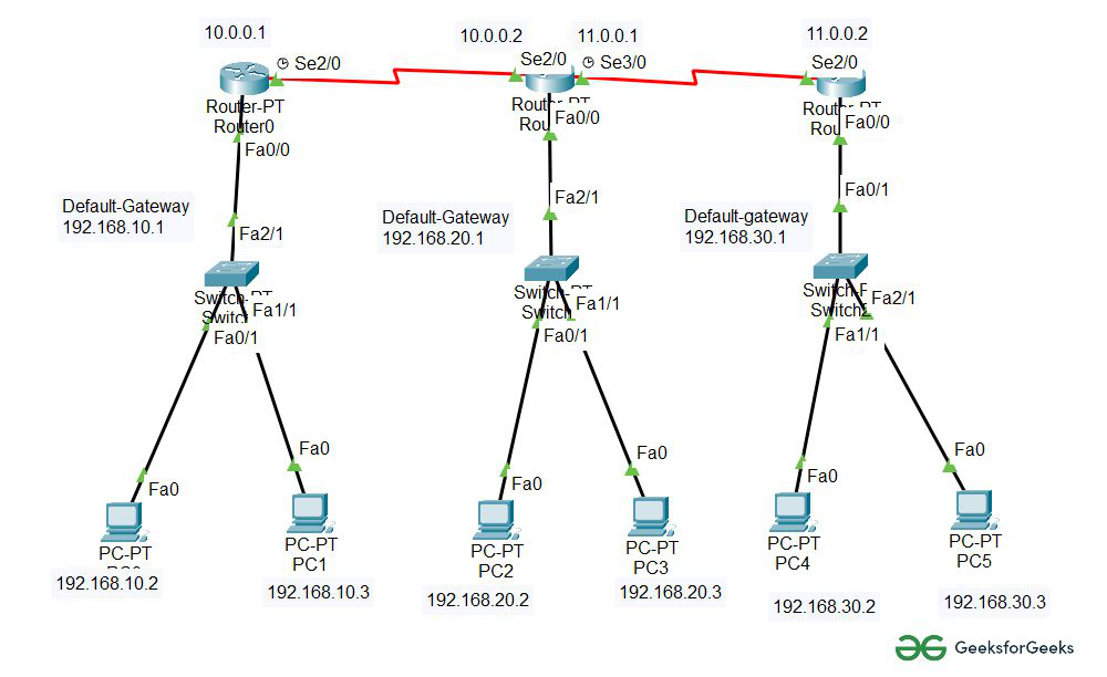
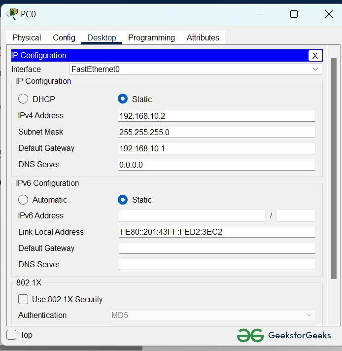
Step 2: Configure the PCs (hosts) with IPv4 address and Subnet Mask according to the IP addressing table given above.
- To assign an IP address in PC0, click on PC0.
- Then, go to desktop and then IP configuration and there you will IPv4 configuration.
- Fill IPv4 address and subnet mask.
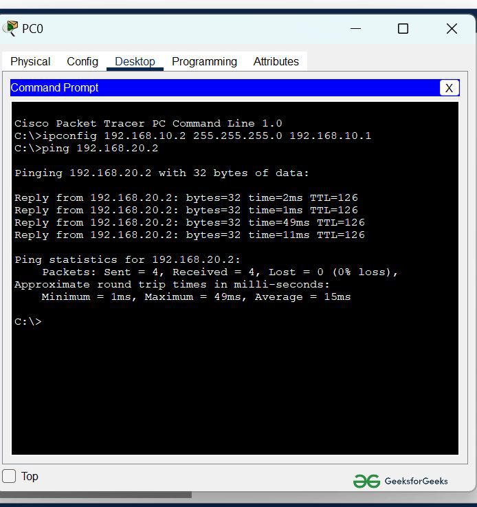
- Assigning an IP address using the ipconfig command, or we can also assign an IP address with the help of a command.
- Go to the command terminal of the PC.
- Then, type iPConfig <IPv4 address><subnet mask><default gateway>(if needed)
Example: iPConfig 192.168.10.2 255.255.255.0 192.168.10.1
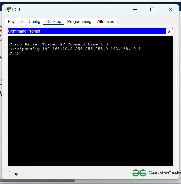
- Repeat the same procedure with other PCs to configure them thoroughly.
Step 3: Configure router with IP address and Subnet mask.
IP Addressing Table Router:
| S.NO | Device | Interface | IPv4 Address | Subnet mask |
|---|---|---|---|---|
| 1. | router0 | FastEthernet0/0 | 192.168.10.1 | 255.255.255.0 |
Serial2/0 | 10.0.0.1 | 255.0.0.0 | ||
| 2. | router1 | FastEthernet0/0 | 192.168.20.1 | 255.255.255.0 |
Serial2/0 | 10.0.0.2 | 255.0.0.0 | ||
Serial3/0 | 11.0.0.1 | 255.0.0.0 | ||
| 3. | router2 | FastEthernet0/0 | 192.168.30.1 | 255.255.255.0 |
Serial2/0 | 11.0.0.2 | 255.0.0.0 |
- To assign an IP address in router0, click on router0.
- Then, go to config and then Interfaces.
- Make sure to turn on the ports.
- Then, configure the IP address in FastEthernet and serial ports according to IP addressing Table.
- Fill IPv4 address and subnet mask.
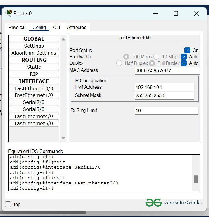
- Repeat the same procedure with other routers to configure them thoroughly.
Step 4: After configuring all of the devices we need to assign the routes to the routers.
To assign RIP routes to the particular router:
- First, click on router0 then Go to CLI.
- Then type the commands and IP information given below.
CLI command : router rip
CLI command : network <network id>
RIP Routes for Router0 are given below:
Router(config)#router rip
Router(config-router)#network 192.168.10.0
Router(config-router)#network 10.0.0.0
RIP Routes for Router1 are given below:
Router(config)#router rip
Router(config-router)#network 192.168.20.0
Router(config-router)#network 10.0.0.0
Router(config-router)#network 11.0.0.0
RIP Routes for Router2 are given below:
Router(config)#router rip
Router(config-router)#network 192.168.30.0
Router(config-router)#network 11.0.0.0
Step 5: Verifying the network by pinging the IP address of any PC.
- We will use the ping command to do so.
- First, click on PC0 then Go to the command prompt.
- Then type ping <IP address of targeted node>.
- As we can see in the below image we are getting replies which means the connection is working properly.
Example : ping 192.168.20.2
- A simulation of the experiment is given below we are sending PDU from PC0 to PC2 and PC3 to PC5:
Idhula irka mari set pannunga

Comments
Post a Comment